
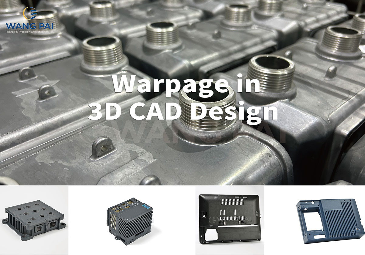
Aluminum Die Casting DFM Guide: Preventing Shrinkage Porosity, Gas Voids, and Warpage in 3D CAD Design
Over 70% of manufacturing defects in aluminum die casting—including internal shrinkage porosity, surface sink marks, cold shuts, and post-demolding warpage—are fundamentally locked in the moment an engineer saves the 3D CAD model.
Many mechanical engineers naturally approach metal parts with a "machining-first" or "injection-molding" mindset. When applied to die casting, this often results in severe structural defects during early mold trials (T0/T1), forcing costly tool revisions, pushing back project timelines, and driving up unit costs.
To bridge the gap between concept and mass production, this Design for Manufacturability (DFM) technical guide breaks down the four core geometry rules engineers must implement directly inside their 3D CAD models.
1. The Core Golden Rule: Transitioning Toward Uniform Wall Thickness
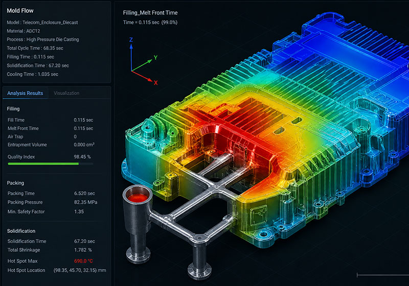
High-pressure die casting (HPDC) involves injecting molten aluminum into hardened tool steel cavities at extreme velocities and pressures, solidifying within milliseconds. Non-uniform cooling rates across varying thicknesses remain the single greatest cause of shrinkage porosity and thermal cracking.
Eliminating "Hot Spots" (Thermal Mass Concentrations)
- The Root Cause: When adjacent wall thicknesses vary drastically—or where perpendicular walls meet without proper coring—a concentrated mass of metal forms a localized "hot spot." The thinner exterior walls cool and freeze first. As the molten aluminum in the thicker core gradually cools and contracts, it cannot draw feed metal from the already solidified surrounding areas, resulting in torn internal cavities known as shrinkage porosity.
-
DFM Strategy:
- Aim for uniform nominal wall thicknesses throughout the casting (ideally between 2.0 mm and 4.0 mm for standard aluminum structural housings).
- Where varying thicknesses are structurally necessary, implement a gradual taper transition with a slope ratio no steeper than 1:3 to 1:4. Never design abrupt 90-degree step transitions.
Strategic Coring (Mass Relieving)
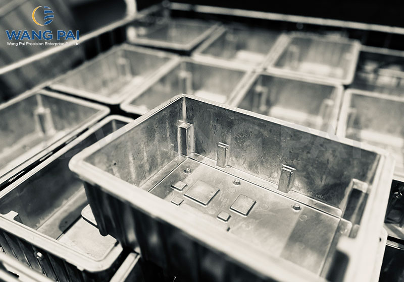
- For structural features such as large mounting bosses, pivot hubs, or heavy flanges, remove excess metal from the non-functional backside or side-action directions using core slides. Hollow out thick masses to preserve consistent wall sections.
2. Geometry Ratios for Ribs and Bosses
Thickening the entire casting simply to boost structural rigidity adds dead weight, lengthens cycle times, and spikes shrinkage defects. In die casting, mechanical stiffness—such as wind-load resistance or torsion control—relies on well-engineered ribs. However, rib dimensions require strict proportional control.
-
Rib-to-Wall Thickness Ratio (
 ):
):
-
The base thickness of a reinforcing rib should be maintained between 60% and 80% of the adjoining nominal wall thickness (
 ).
). - Engineering Risk: A 1:1 thickness ratio creates an inescapable hot spot at the junction, resulting in visible sink marks on the opposing cosmetic surface and hidden internal porosity.
-
The base thickness of a reinforcing rib should be maintained between 60% and 80% of the adjoining nominal wall thickness (
- Internal and External Fillets:
-
Eliminate sharp corners. Internal transition radii should measure between 0.5 to 1.0 times the nominal wall thickness (minimum standard:
 ).
). - Generous fillets eliminate sharp stress concentrations, ease smooth aluminum flow during high-speed cavity filling, and significantly reduce tool erosion and air entrapment.
- Standalone cylindrical bosses disrupt metal flow fronts, causing turbulent swirls and trapped gas. Always tie standalone bosses to adjacent perimeter walls using thin gussets or ribs to ensure smooth liquid metal delivery.
- Self-Supporting Boss Geometry:
3. Draft Angles and Ejection Reliability
As aluminum alloys cool and solidify in the die, they shrink toward internal cores and away from outer cavity walls. Insufficient draft angles generate severe friction upon tool opening, causing galling, surface drag marks, and bent ejector pins.
-
Inner Walls and Cores:
-
Because aluminum shrinks tightly onto steel core pins, interior features require a larger draft angle. Specify between
 of draft.
-
Because aluminum shrinks tightly onto steel core pins, interior features require a larger draft angle. Specify between
- Outer Enclosure Walls:
-
As the metal pulls away from the outer cavity during cooling, outer features require less relief. A draft angle of
 is generally sufficient.
 - For cast-in holes intended for tapping, hole depth should not exceed 3 to 4 times the hole diameter. Overly slender core pins overheat, suffer high deflection, and risk fatigue fractures under cyclic mechanical ejection stresses.
- Cored Hole Depth Limits:
4. Symmetric Geometry: Controlling Residual Stress and CNC Warpage
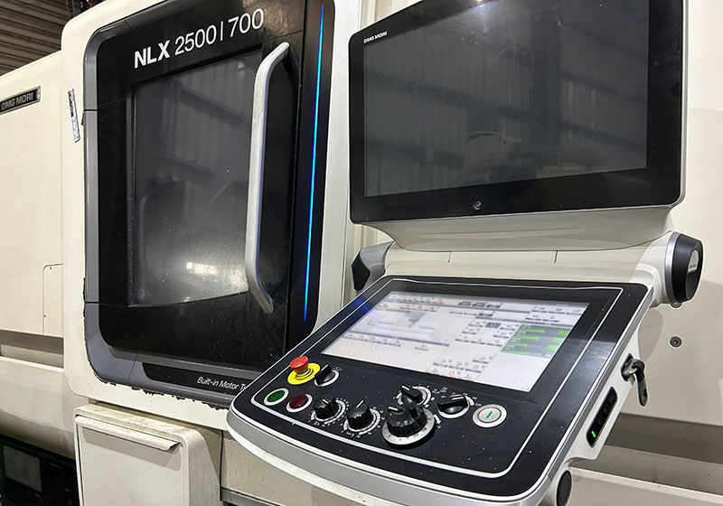
A die-cast housing may measure perfectly within geometric tolerance immediately after demolding, only to twist out of spec once clamped and cut in a CNC machining center. This is caused by unbalanced residual thermal stresses within the raw casting.
-
Thermal Stress Balance:
- Strive for geometric symmetry across primary axes. If one side of an enclosure features dense heat-dissipation fins while the opposite side is a smooth plate, uneven cooling rates will pull the housing toward the finned side. Balance thermal mass to equalize cooling shrinkage.
- Cast-In Locating Datums (3-2-1 Principle):
- Define three primary, non-machined cast datum pads directly in the 3D model. Locate these datums far away from parting lines, gating runners, and overflow vents. This ensures your CNC fixture can repeatedly seat and clamp the component without inducing mechanical deflection or twisting the sealing surface out of plane.
Quick CAD DFM Checklist
|
Design Parameter |
Recommended Standard |
Engineering Failure Prevented |
|---|---|---|
|
Nominal Wall Thickness |
|
Shrinkage porosity, cold shuts, flow lines |
|
Rib Base Thickness |
|
Cosmetic sink marks, internal hot spots |
|
Fillet Radii |
|
Stress cracking, turbulent flow, cavity erosion |
|
Draft Angle (Internal) |
|
Core galling, surface scoring, ejection warping |
|
Draft Angle (External) |
|
Cavity dragging, cosmetic scuffing |
|
Structural Balance |
Symmetrical rib/fin layout |
Post-cooling bow, distortion after CNC finishing |
 , gradual transition (
 )
) of nominal wall
 (no sharp
  corners)

Further Reading:
 Can aluminum alloy materials withstand polar climates?
The importance of airtightness
Differentiation of die-cast aluminum industrial control displays
Learn more about Aluminum Die Casting Features
Browse Aluminum Die Casting Exhibits
Product development OEM consulting